
LHF / LJF
Hydraulic Prefill Valve
LHF & LJF Sandwich type, two different materials.
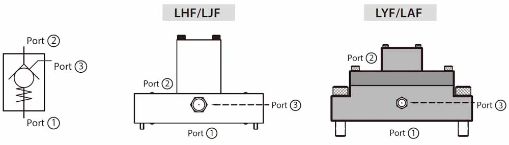
━Symbol
━DESCRIPTION
The working principal of prefill valve is like pilot-to-open check valve. It allows free flow from the port 2 to port 1 and blocks flow in the opposite direction. Pressure at pilot port (port 3) will open the valve from port 1 to port 2.
In case any shock, noise and system damage, please make sure it has already completely decompression at port 1 then pilot to open the prefill valve allowing flow from port 1 to port 2. When pilot port is blocked, prefill valve acts like a large
capacity check valve. LINS hydraulics provides two types and two materials prefill valve, including sandwich and flange mounting type, alloy steel (SCM440) and cast iron (FCD50).
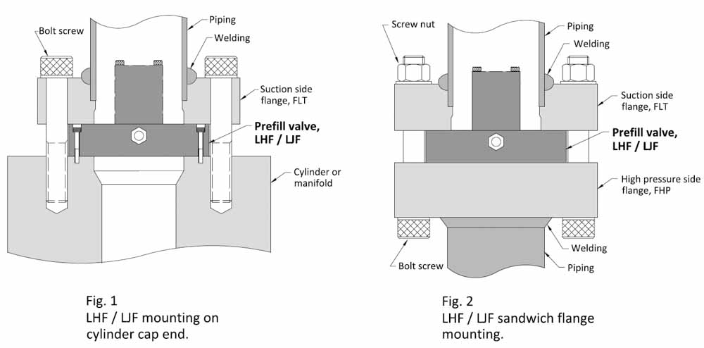
It can be directly fitted on the cylinder cap end or mounting on piping flange in the hydraulic systems. The operating pressure up to 400 bar (5800 PSI), capacity up to 15000 LPM (4000 GPM).
━FEATURE
l Compact size & easy installation.
l High pressure, high durability.
l High capacity and low-pressure loss.
l Sandwich and flange mounting type.
l Two materials, alloy steel and cast iron.
l Directly mount on cylinder cap end.
█ ORDER CODE
|
LHF |
- |
100 |
|
① |
② |
①: Series
LHF: Sandwich type, SCM440 material.
LJF: Sandwich type, FCD50 material.
②: Valve size
32 – 250
(See dimension table for reference)
█ LHF / LJF DIMENSIONAL DRAWING
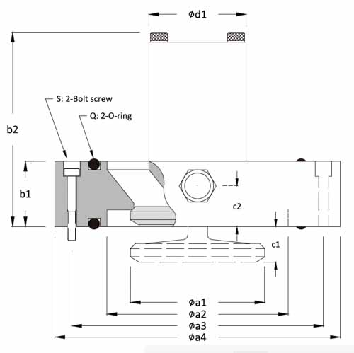
Notice:
1. Attention for poppet working space c1.
2. LINS offer the suction side flange with LYF and LAF prefill valve. For LHF and LJF series, flange must order separately.
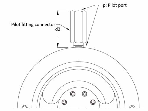
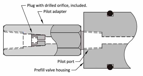
3. All LINS prefill valves including a pilot port adapter with orifice plug, see table for orifice and plug size.
█ LHF / LJF Dimension Table (mm)
|
p |
S |
Q |
Model |
øa1 |
øa2 |
øa3 |
øa4 |
b1 |
b2 |
c1 |
c2 |
ød1 |
d2 |
|
|
1/4" PT |
- |
AS228 |
LHF32 |
LJF32 |
34 |
49 |
- |
82 |
28 |
70 |
7.5 |
15 |
33 |
62 |
|
1/4" PT |
M4 x 30 |
AS231 |
LHF40 |
|
42 |
56.5 |
91 |
108 |
28 |
76.5 |
10 |
16.5 |
39 |
62 |
|
1/4" PT |
M4 x 30 |
AS236 |
LHF50 |
LJF50 |
53 |
72 |
112 |
128 |
29 |
91 |
12.5 |
16 |
42 |
62 |
|
1/4" PT |
M5 x 35 |
P95 |
LHF63 |
LJF63 |
63 |
87 |
125 |
143 |
33.5 |
105 |
16 |
18.5 |
50 |
62 |
|
1/4" PT |
M5 x 40 |
P120 |
LHF80 |
LJF80 |
78 |
108 |
150 |
169 |
38.5 |
117 |
17 |
24 |
57 |
62 |
|
1/4" PT |
M6 x 45 |
P145 |
LHF100 |
LJF100 |
97 |
130 |
185 |
210 |
44 |
150 |
22 |
29 |
70 |
62 |
|
3/8" PT |
M6 x 50 |
P185 |
LHF125 |
LJF125 |
128 |
170 |
226 |
248 |
51 |
190 |
32 |
35 |
89 |
70 |
|
3/8" PT |
M8 x 70 |
P235 |
LHF160 |
|
160 |
220 |
284 |
310 |
70 |
225 |
37 |
50 |
120 |
70 |
|
1/2" PT |
M10 x 95 |
P295 |
LHF200 |
|
200 |
272 |
355 |
390 |
95 |
286 |
50 |
65 |
145 |
85 |
|
1/2" PT |
M12 x 115 |
P385 |
LHF250 |
|
250 |
350 |
445 |
490 |
110 |
372 |
70 |
70 |
177 |
85 |
█ LHF / LJF Specification
|
Model |
Max. Pressure |
Max. Flow |
Piping port |
Pilot ratio |
Gross Weight |
|
|
(Bar) |
(LPM) |
|
|
(Kg) |
||
|
LHF32 |
LJF32 |
400 / 250 |
160 |
2B |
3.6 |
1.3 /1.2 |
|
LHF40 |
|
400 |
250 |
2.5B |
3.6 |
2.2 |
|
LHF50 |
LJF50 |
400 / 250 |
400 |
3B |
4.5 |
3.2 / 3.0 |
|
LHF63 |
LJF63 |
400 / 250 |
630 |
3.5B |
4.4 |
4.5 / 4.2 |
|
LHF80 |
LJF80 |
400 / 250 |
1000 |
4B |
4.6 |
6.8 / 6.4 |
|
LHF100 |
LJF100 |
400 / 250 |
1600 |
5B |
4.6 |
12.3 / 11.7 |
|
LHF125 |
LJF125 |
400 / 250 |
2500 |
8B |
4.5 |
20.5 / 19.3 |
|
LHF160 |
|
400 |
4000 |
10B |
4.3 |
45 |
|
LHF200 |
|
280 |
7000 |
12B |
4.3 |
98 |
|
LHF250 |
|
280 |
15000 |
16B |
4.5 |
178 |
█ Pilot Port Adapter Schematic & Dimension Table
|
Model |
orifice plug |
orifice size (mm) |
|
LHF LJF LYF LAF-32 40 50 |
1/8" PT |
0.7 |
|
LHF LJF LYF LAF-63 |
0.8 |
|
|
LHF LJF LYF LAF-80 |
1.0 |
|
|
LHF LJF LYF LAF-100 |
1.2 |
|
|
LHF LJF LYF LAF-125 160 |
1/4" PT |
1.5 |
|
LHF LJF LYF LAF-200 250 |
none |
none |
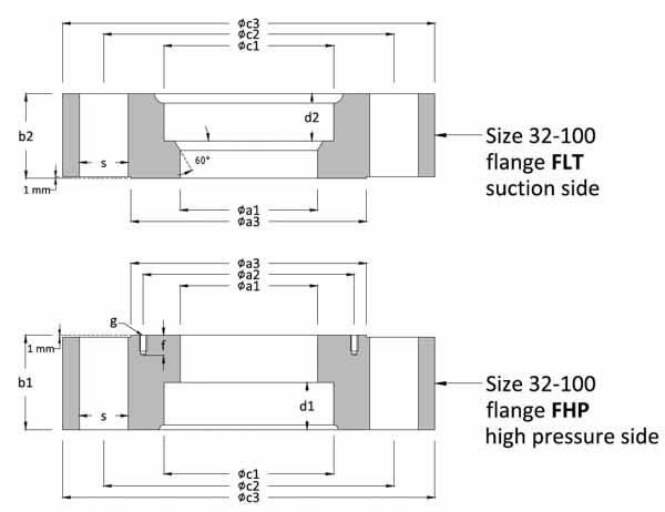
█ LHF / LJF Flange Dimension (mm), Size 32-100
|
Piping port |
s |
g |
f |
d1 |
d2 |
Flange Model |
øa1 |
øa2 |
øa3 |
øb1 |
øb2 |
øc1 |
øc2 |
øc3 |
|
2B |
4-ø17.5 |
- |
- |
20 |
- |
FHP-32-A |
48 |
- |
82 |
35 |
- |
61.1 |
103.2 |
135 |
|
- |
20 |
FLT-32-A |
- |
35 |
||||||||||
|
2.5B |
4-ø22 |
2-M4 |
10 |
22 |
- |
FHP-40-A |
57 |
91 |
107 |
44 |
- |
77.1 |
130.1 |
165 |
|
- |
22 |
FLT-40-A |
- |
44 |
||||||||||
|
3B |
6-ø18 |
2-M4 |
10 |
20 |
- |
FHP-50-A |
73 |
112 |
125 |
40 |
- |
90 |
146 |
180 |
|
- |
20 |
FLT-50-A |
- |
40 |
||||||||||
|
6-ø26 |
25 |
- |
FHP-50-B |
50 |
- |
154 |
198 |
|||||||
|
- |
25 |
FLT-50-B |
- |
45 |
||||||||||
|
3.5B |
8-ø18 |
2-M5 |
10 |
20 |
- |
FHP-63-A |
88 |
125 |
140 |
42 |
- |
102 |
161 |
198 |
|
- |
12 |
FLT-63-A |
- |
35 |
||||||||||
|
8-ø26 |
27 |
- |
FHP-63-B |
55 |
- |
169 |
214 |
|||||||
|
- |
27 |
FLT-63-B |
- |
50 |
||||||||||
|
4B |
8-ø18 |
2-M5 |
10 |
20 |
- |
FHP-80-A |
108.5 |
150 |
166 |
45 |
- |
115 |
187 |
220 |
|
- |
15 |
FLT-80-A |
- |
35 |
||||||||||
|
8-ø26 |
27 |
- |
FHP-80-B |
65 |
- |
195 |
240 |
|||||||
|
- |
27 |
FLT-80-B |
- |
55 |
||||||||||
|
5B |
8-ø23 |
2-M6 |
10 |
25 |
- |
FHP-100-A |
132 |
185 |
210 |
65 |
- |
141 |
236 |
280 |
|
- |
20 |
FLT-100-A |
- |
55 |
||||||||||
|
8-ø33 |
30 |
- |
FHP-100-B |
80 |
- |
244 |
300 |
|||||||
|
- |
30 |
FLT-100-B |
- |
70 |
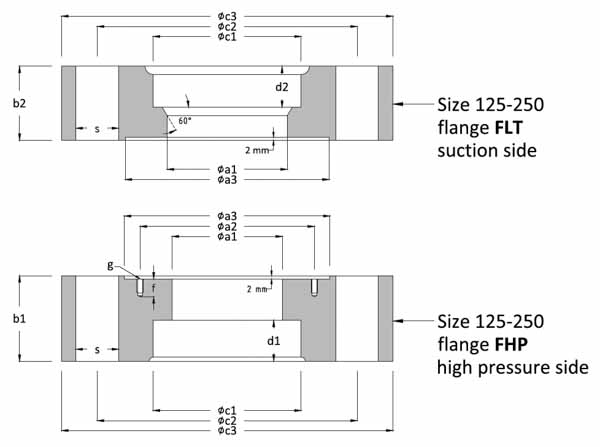
█ LHF / LJF Flange Dimension (mm), Size 125-250
|
Piping port |
s |
g |
f |
d1 |
d2 |
Flange Model |
øa1 |
øa2 |
øa3 |
øb1 |
øb2 |
øc1 |
øc2 |
øc3 |
|
8B |
12-ø26 |
2-M6 |
15 |
35 |
- |
FHP-125-A |
168 |
226 |
249 |
70 |
- |
219 |
300 |
350 |
|
- |
25 |
FLT-125-A |
- |
60 |
||||||||||
|
12-ø32 |
50 |
- |
FHP-125-B |
90 |
- |
354 |
||||||||
|
- |
30 |
FLT-125-B |
- |
80 |
||||||||||
|
10B |
16-ø32 |
2-M8 |
15 |
40 |
- |
FHP-160-A |
218 |
284 |
312 |
90 |
- |
270 |
367 |
422 |
|
- |
30 |
FLT-160-A |
- |
80 |
||||||||||
|
12B |
20-ø32 |
2-M10 |
20 |
40 |
- |
FHP-200-B |
270 |
355 |
392 |
100 |
- |
321 |
442 |
510 |
|
- |
35 |
FLT-200-B |
- |
90 |
||||||||||
|
16B |
24-ø32 |
2-M12 |
25 |
55 |
- |
FHP-250-A |
350 |
445 |
495 |
110 |
- |
409 |
555 |
632 |
|
- |
40 |
FLT-250-A |
- |
100 |
||||||||||
|
18B |
22-ø45 |
55 |
- |
FHP-250-B |
125 |
- |
460 |
|||||||
|
- |
40 |
FLT-250-B |
- |
110 |
█ LHF / LJF Flange order code
|
FHP |
- |
100 |
- |
A |
|
① |
② |
③ |
①: Series
FHP: High pressure side flange.
FLP: Suction side flange.
②: Flange size, see flange dimension table for reference.
③: Flange thickness
A: Standard thickness
B: Thickened thickness
*The provided flange dimension is for LHF and LJF series, please order separately. For LYF & LAF series, we offer a suction side flange kit with the prefill valve.
█ LHF / LJF Assembly Schematic
█ Application Circuit
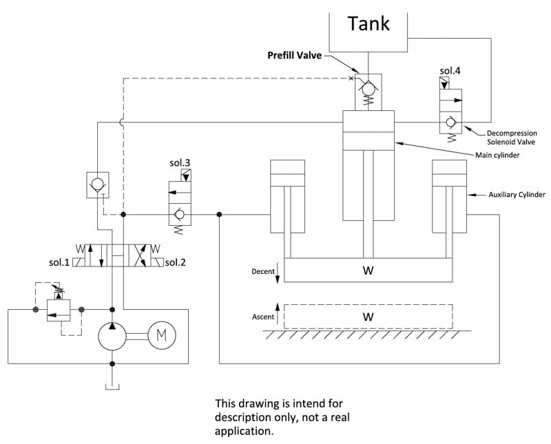
Example of prefill valve circuit on a pressing motion.
|
Main Cylinder |
Sol.1 |
Sol.2 |
Sol.3 |
Sol.4 |
Prefill Valve |
|
rod descending |
v |
|
v |
|
suction mode |
|
chamber pressurized |
v |
|
v |
|
closed |
|
pressure retaining |
|
|
|
|
closed |
|
rod ascending |
|
v |
|
v |
pilot open |
Consideration:
1. Make sure the pressure at main cylinder cap side has completely decompression when cylinder is retracted.
2. It can connect a needle valve with decompression solenoid valve (sol.4) to control the decompression time.